A story about home automation
June 01, 2015

relay circuits are "hello word" projects of electronic prototyping. Long time ago, when got my first computer i created one of them and controlled the desktop peripherals via pc software. this kind of desktop automation can really save your life if you have ADHD or something. first prototype was driven via parallel port and a visual basic application was controlling directly the motherboard resources w/o any kernel driver or something.
at the beginning, i realized the this kind of setup causing the electromagnetic interference due to mechanical relays. and eventually causing BSOD. someday i decided to create another relay box from scratch by using PIC16F877 so relay box will be declare the it's independence, as the result we won't need to worry about bsod's. i was controlling it via comport and bundled another PIC controller to reset the circuit in spesific time period. with this setup device can continue to work even if microcontroller frozen or stuck which caused by EMI
Second attempt was in 2009, i met with the arduino in this year and created same relay box by using uno board and one relay module which purchased from ebay. i was hoping this kind of "ready to use" components will be completely robust and stable instead of my handmade boards.
But it's not! I still messed with EMI problems and headed to another rubbish idea. this time, provided power to +12v relays by using set of +5v small relays which connected to arduino. and one of them was bridged with a bigger relay called contactor which designed to handle heavy electical loads. as the result, i was solved the emi problem by using three level of isolated circuits but wasted 9 relays just for 3 power outlet.
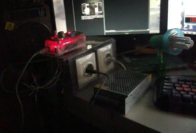
Modernization Here's the starting point of this entry. the second version (black box on the picture) still working without any problem but it's getting obsolete. making too much noise, drawing unnecessary power etc.
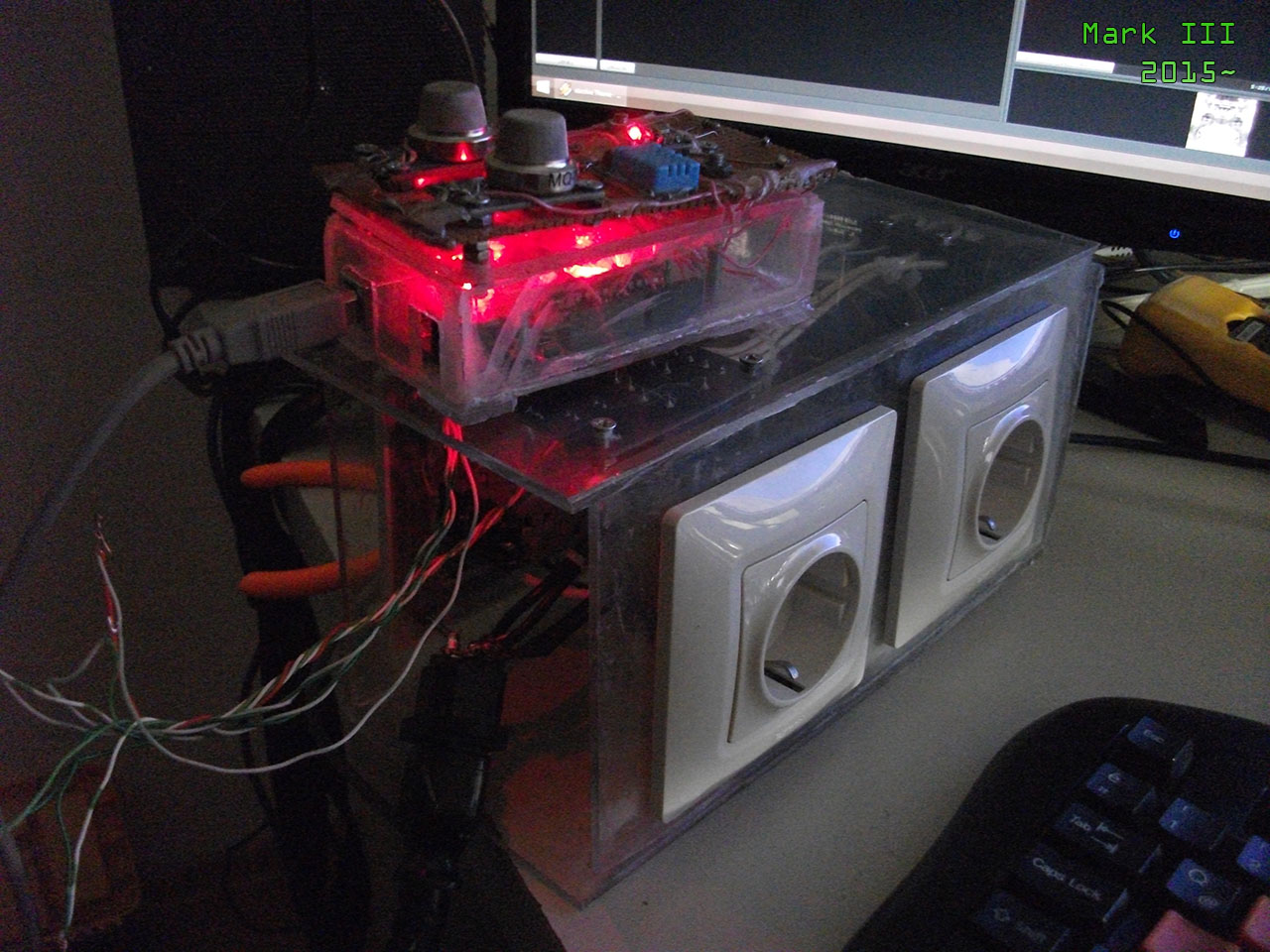
few weeks ago researched the solid state relay modules and decided to create a final version which will lasts about another 10 year. ssr relays are working like mosfets so they're completely emi-free. i purchased a relay module and another arduino board and just connected them together within one hour. then i found the enough time to focus the box design and it's firmware.
as the result, final version costs me about $35~40 plus two weeks. now it's completely silent, stable and powered directly from usb which cannot draw more than +5v ~ 500 milliamps.
Assignment another software controlling that box to turn on desktop peripherals upon pc boot and turning off them when user away from computer to save energy. actually that's not a big deal but this kind of small details really increasing the life quality and returns as motivation which required for development of more bigger things.
If interested, it's source code available in devzone section.


